Wiring Diagram Ladder
The PLC reads a Ladder Diagram from left to right top to bottom in the same general order as a human being reads sentences and paragraphs written in English. And that is just the beginning.

Nand Gate Electrical Wiring Diagram Nand Gate Ladder Logic
It is clear and understandable.

Wiring Diagram Ladder. PLC Wiring Basics. At the end of this article I will share LD examples that will get. Introduction to PLC ladder diagrams.
It will continue downward as you will see later on. Read a basic ladder logic diagram and statement list Identify operational differences between different S7-200 models Identify the proper manual to refer to for programming or installation of an S7-200 PLC Connect a simple discrete input and output to an S7-200 Select the proper expansion module for analog inputs and outputs. A wiring diagram is an electrical print that shows connections of all components in a piece of equipmentA schematic diagram is a type of drawing that illustrates the electrical connections and functions of specific circuit arrangements with graphic symbolsA ladder diagram is a diagram that explains the logic of the electrical circuit or system using standard NEMA or IEC symbols.
If you are still a little confused about the different PLC wiring and ladder diagram symbol combinations and their different logic states thenDONT PANIC. A schematic or schematic diagram is a representation of the elements of a system using abstract graphic symbols rather than realistic pictures. Logic Diagram pictorial diagram.
Two-way switches and three-way switches operate the same way and have the same connection points they just have different names in the UK which are Common L1 and L2. Thermostat Wiring Diagrams White-Rodgers shows a slightly different type of wiring diagram that mirrors a ladder logic diagram. It is called ladder because the symbols that are used to represent the components in the system have been placed on the rungs of a ladder.
In the ladder diagram the programming language that used to create the program to control the PLC system is known as Ladder Diagram Language or Ladder Logic Language. You Will Love This Easy-To-Use Diagram Software. This diagram shows what each terminal designation that goes to the HVAC system.
Now these diagrams are known as relay logic or ladder diagrams. Edraw Max is perfect not only for professional-looking flowcharts organizational charts mind maps but also network diagrams floor plans workflows fashion designs UML diagrams electrical diagrams science illustration charts and graphs. Lets take a look.
Wiring diagrams can be helpful in many ways including illustrated wire colors showing where different elements of your project go using electrical symbols and showing what wire goes where. UK two-way switch wiring diagram. Ladder logic was designed to have the same look and feel as electrical ladder diagrams but with ladder logic the physical contacts and coils are replaced with memory bits.
Ladder diagrams will be referred to as schematic diagrams or simply schematics. A Very Useful Blog About Electrical Engineering Technology Electrical Wiring- EE-Calculator EE Q-A EE Notes Motors Power System ControlEducationCareer. 1756 ControlLogix 1756 GuardLogix 1769 CompactLogix 1769 Compact GuardLogix 1789 SoftLogix 5069.
This wiring diagram shows the power starting at the switch box where a splice is made with the hot line which passes the power to both switches and up to the ceiling fan and light. The molecular orbital energy-level diagram which is a diagram that shows the relative energies of molecular orbitals for the H 2 molecule is shown in Figure On either side of the central ladder are shown the energies of the 1 s orbitals of atoms A and B and the central two-rung ladder shows the energies of the bonding and antibondingThe. To help out weve developed a nifty table which displays the different combinations of PLC digital input wiring and ladder logic symbols that can be used.
For this program the relay logics ladder diagram is duplicated with ladder logic. It is the most common type of wiring Diagrams. Now in the diagram below I have added a motor starter.
No more hard-wired logic but memory locations instead. A schematic usually omits all details that are not relevant to the key information the schematic is intended to convey and may include oversimplified elements in order to make this essential meaning easier to grasp. Its using relays to control the circuit and also the diagram will begin to take the shape of a ladder as the relay logic grows.
T he Constructor program makes the creation testing trouble-shooting teaching and printing of electrical ladder diagrams diagram schematics electrical wiring diagrams electrical drawings and one line diagrams fast and easy. At least to an expert. There you have it.
However according to the IEC 61131-3 standard a PLC program must evaluate read all inputs contacts to a function before determining the status of a functions output coil or coils. Block Diagram electrical drawing pdf Ladder Diagram or Line Diagram. This is one of the areas that show up as problems if the designinstallation team are not normally controls oriented.
This is also an area that causes a lot of rework on the part of the installers and the integrators when they meet during checkout onsite. In the United Kingdom some electricians use an alternative method for wiring two-way switches as depicted in the above wiring diagram. Programming Manual Original Instructions Logix 5000 Controllers Ladder Diagram.
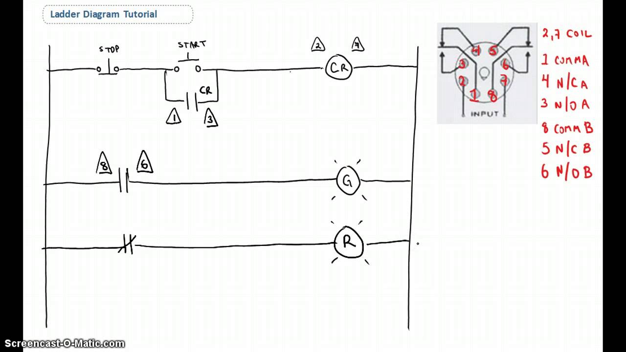
A non-aluminum ladder and Voltage Tester. This is why a good diagram is important for wiring your home accurately and according to electrical codes. As an introduction to ladder diagrams consider the simple wiring diagram for an electrical circuit in Figure 1aThe diagram shows the circuit for switching on or off an electric motor.
Depends on personal level experience ability to work with tools and access to the ceiling fan. It has signified by the graphical representation just like electrical wiring for logic control. The circuit will perform the same as a hard wired electrical circuit.
Keep your diagram nearby. Failsafe wiring practice is one of those topics that separates control system designers and electricians from other technical specialties. The design can be edited and re-tested saving valuable time when it comes to hard wired circuits.

Plc Application For Reduced Voltage Start Motor Control Eep Ladder Logic Basic Electrical Wiring Electrical Circuit Diagram
Ladder Diagram Basics 1 Diagram Ladder Logic Symbols

Free Editable Ladder Electrical Wiring Diagram Edrawmax In 2021 Electrical Wiring Diagram Diagram Electrical Wiring

Plc Control Panel Wiring Diagram On Plc Panel Wiring Diagram Electrical Circuit Diagram Electricity Diagram

Fatek Wiring Diagram Plc Http Bookingritzcarlton Info Fatek Wiring Diagram Plc

Free Editable Combination Of Wiring And Ladder Diagram Example Edrawmax In 2021 Electrical Wiring Diagram Diagram House Wiring

Free Editable Ladder Line Wiring Diagram Edrawmax In 2021 Electrical Wiring Diagram Diagram Electrical Wiring

Connection Diagram From The Plc To The Vs Drive S Terminal Block Ladder Logic Plc Programming Circuit Diagram

Pin On Electronics

Ladder Wiring Diagrams Wiring Diagramelectrical Wiring Ladder Diagram As Well Function Types Of Electrical Wiring Electrical Wiring Diagram Electrical Diagram

Plc Program For Temperature Control Using Thermostat Ladder Logic Mechanical Projects Programmable Logic Controllers
Conveyor Belt Control Using Plc Ladder Logic Programmable Logic Controllers Electronics Basics

Star Delta Motor Plc Ladder Logic Ladder Logic Electrical Circuit Diagram Logic

Anti Plugging Circuit Ladder Logic Electrical Circuit Diagram Electrical Diagram

Electrical Plc Wiring Diagram On Counters In Ladder Diagrams Ladder Logic Ford Courier Logic Programming

Plc Program For Bottle Filling Ladder Logic Ladder Logic Electrical Circuit Diagram Logic Programming

Plc Programming Basics Using Ladder Logic Plc Programming Ladder Logic Learn Robotics

Types Of Electrical Drawing And Diagrams Electrical Technology Electrical Diagram Electricity Single Line Diagram

Plc Program Example With Toggle Or Flip Flop Function Ladder Logic Plc Programming Logic


Comments
Post a Comment